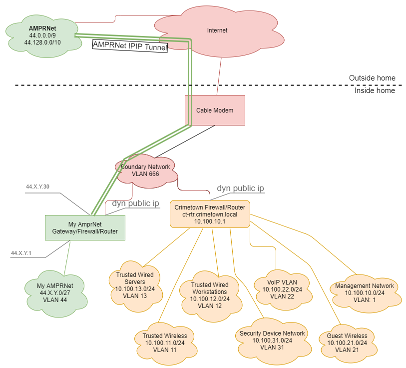
NOTE: 2023-11-14 This information is outdated, and will be updated on a future modification. While the logical network largely remains the same, I have rebuilt the network using TP-Link Omada gear using a TP-Link OC controller, TP-Link Router, two TP-Link switches, and two TP-Link Access Points.
NOTE: 2025-06-26 This information is outdated, and will be updated on a future modification. While the logical network largely remains the same, I have rebuilt the network using Ubiquity UniFi gear.
Below you will find some information regarding the networking setup I am using. This is mostly for my reference, but I am posting it as it may help others in some way.

Information regarding the AMPRNet Configuration will be posted in the Amateur Radio section of this site, but it is not yet posted. In the diagram above, I have removed the second and third octet of my assigned AMPRNet network address and replaced them with X and Y. This will be done throughout my website so if anyone references any of my documentation they know to replace this their assigned network information.
Below is the VLAN and port configuration on the CT-RTR Router (dated – needs updating).
VLAN Configuration
VLAN 001 - 10.100.10.0/24 - Management Network (No DHCP)
  No DHCP
  CT-RTR.crimetown.local Address 10.100.10.1

VLAN 011 - 10.100.11.0/24 - Trusted Wireless
  DHCP Range 10.100.11.50 - 99
  Gateway Address 10.100.11.254

VLAN 012 - 10.100.12.0/24 - Trusted Wired Workstations
  DHCP Range 10.100.12.50 - 99
  Gateway Address 10.100.12.254

VLAN 013 - 10.100.13.0/24 - Trusted Wired Servers (No DHCP)
  No DHCP
  Gateway Address 10.100.13.254
  CT-PI.crimetown.local     Address 10.100.13.100
  CT-PISTAR.crimetown.local Address 10.100.13.101

VLAN 021 - 10.100.21.0/24 - Guest Wireless (internet only)
  DHCP Range 10.100.21.50 - 99
  Gateway Address 10.100.21.254

VLAN 022 - 10.100.22.0/24 - VoIP Network (internet only)
  DHCP Range 10.100.22.50 - 99
  Gateway Address 10.100.22.254

VLAN 031 - 10.100.31.0/24 - Security Network (non-routable, No DHCP)
  No DHCP
  Gateway Address 10.100.31.254

VLAN 044 - No Net - AMPRNet (non-routable, No DHCP)
  No DHCP
  No Gateway

VLAN 666 - No Net - Boundary Network (non-routable, No DHCP)
  No DHCP
  No Gateway

VLAN 999 - No Net - Parking Lot (non-routable, No DHCP)
  No DHCP
  No Gateway Address


Cisco RV325 Port config
Port 01 - Access VLAN11
Port 02 - Tagged VLAN1,11,21         (WAP port)
Port 03 - Access VLAN22              (VoIP ATA Device)
Port 04 - DISABLED - Access VLAN 12
Port 05 - Access VLAN13              (Raspberry Pi)
Port 06 - DISABLED - Tagged VLAN13,31
Port 07 - DISABLED - Access VLAN 999
Port 08 - Access VLAN12
Port 09 - DISABLED - Access VLAN 999
Port 10 - DISABLED - Access VLAN31    (Future Use for PoE Cameras)
Port 11 - DISABLED - Access VLAN31    (Future Use for PoE Cameras)
Port 12 - DISABLED - Access VLAN999
Port 13 - DISABLED - Access VLAN999
Port 14 - Access VLAN1                (Dedicated Management access port)
Port 15 - WAN1                        (Internet Port)
Port 16 - WAN2 - DISABLED
